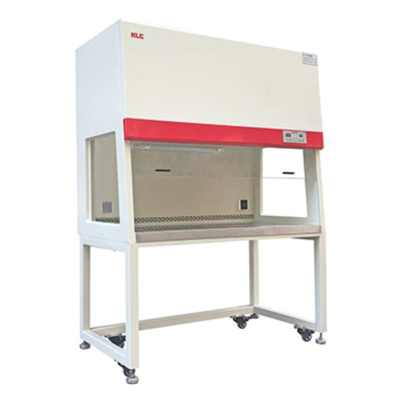
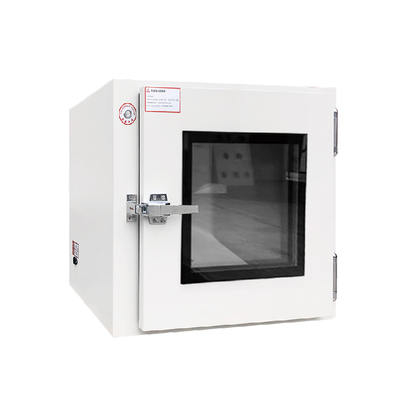
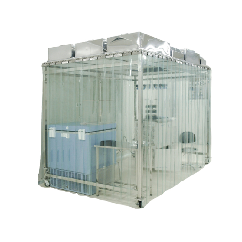
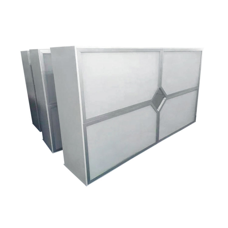
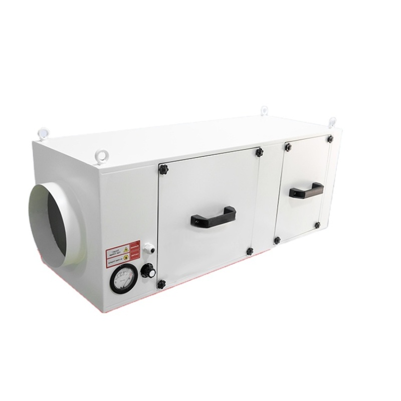
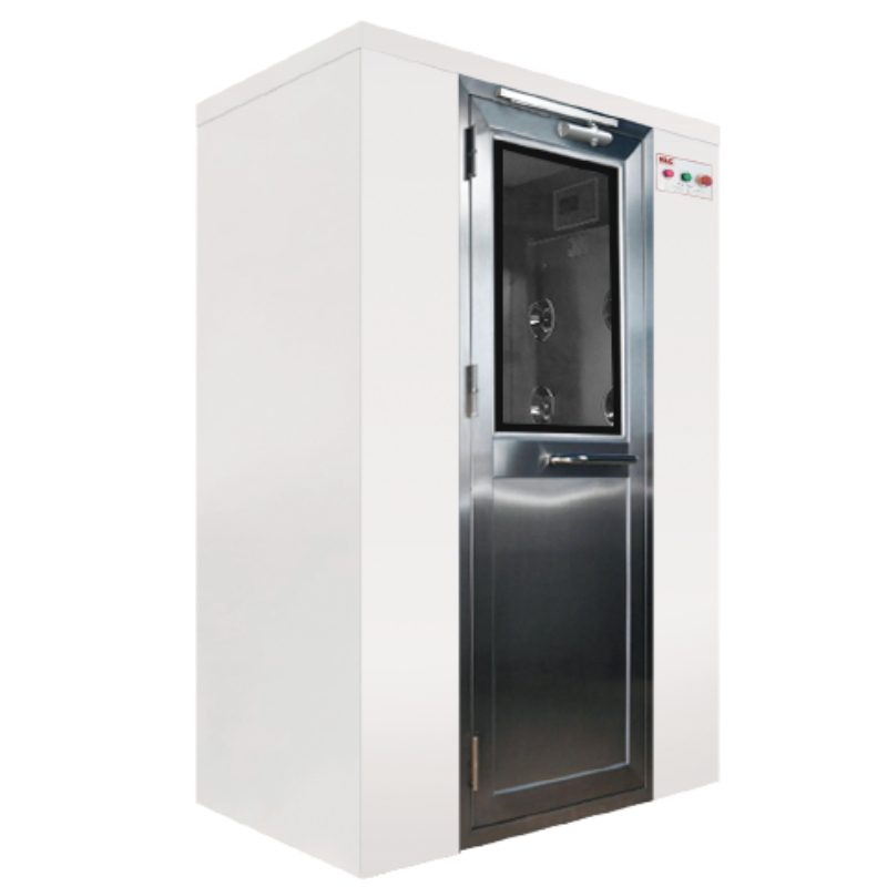
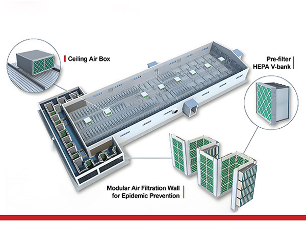
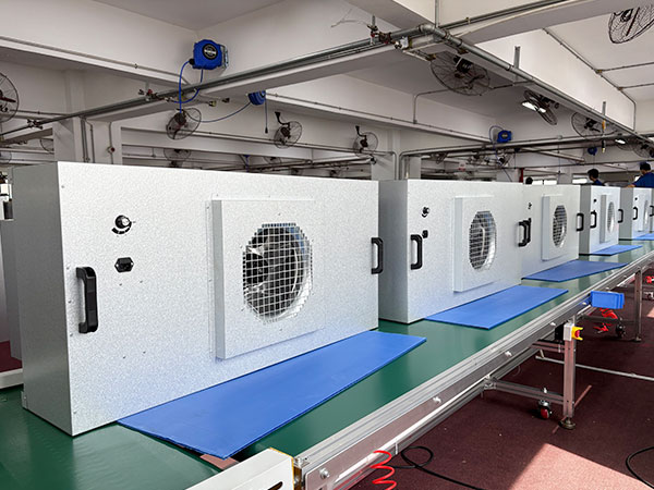
Applications
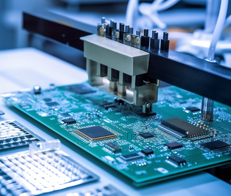
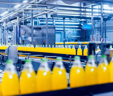
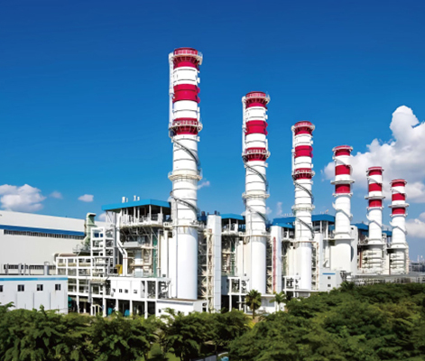
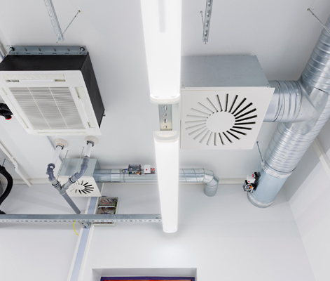
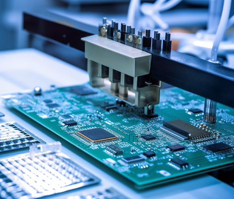
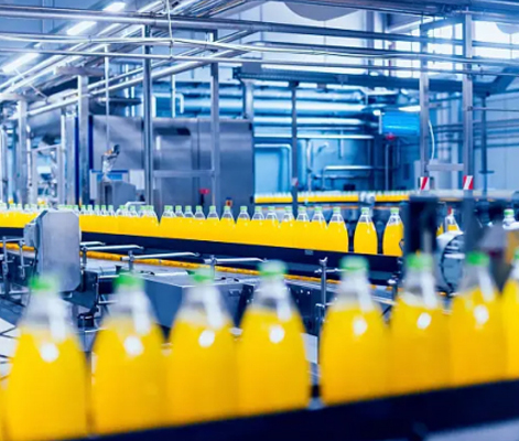
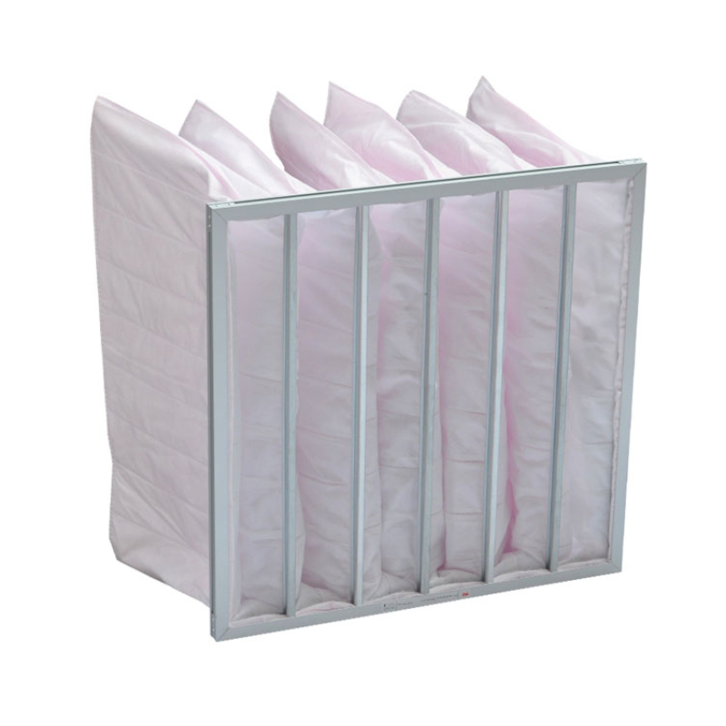
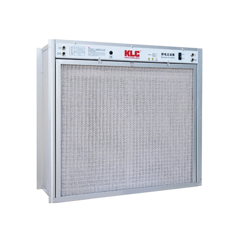
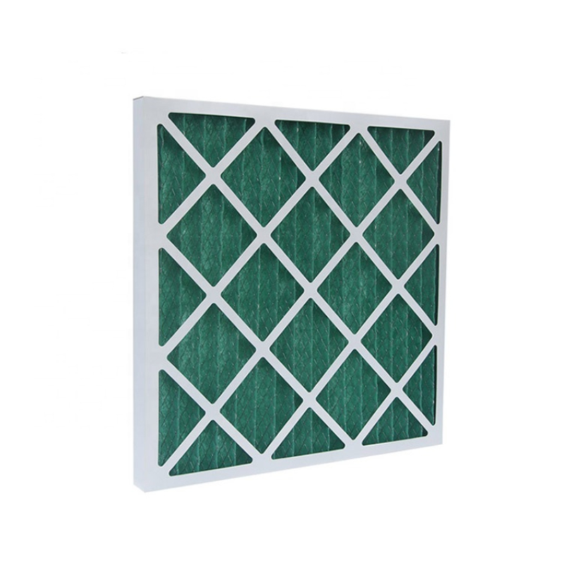
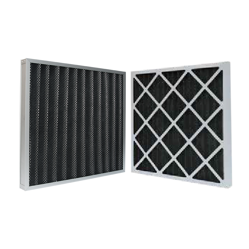
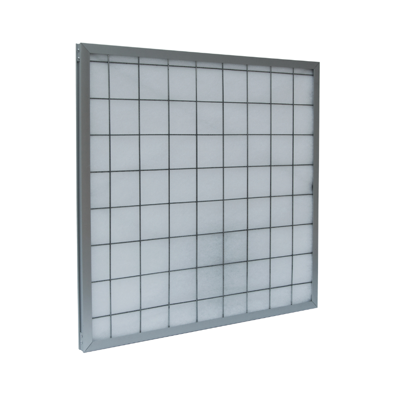
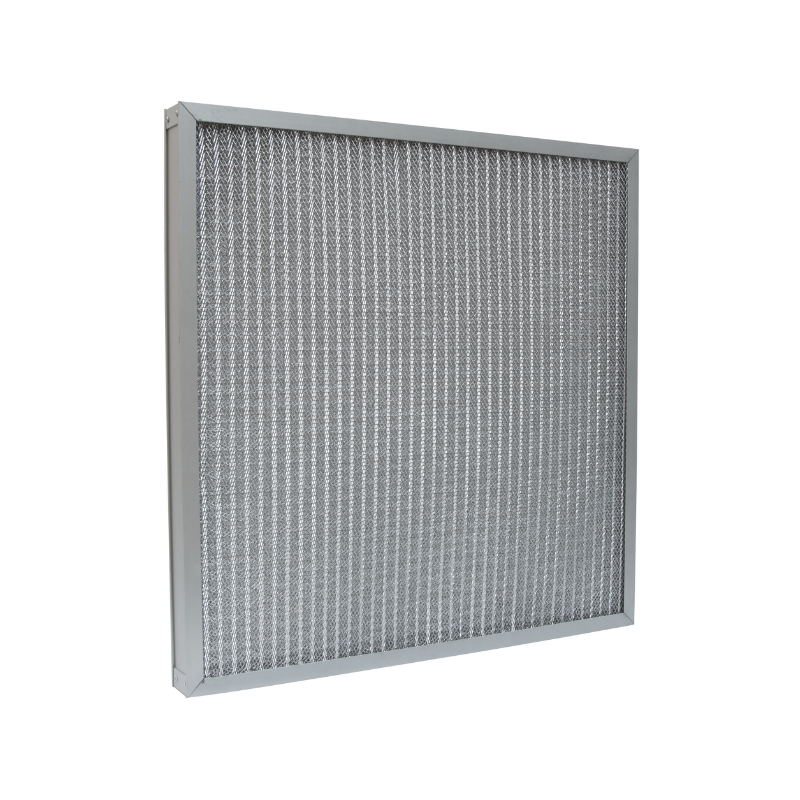
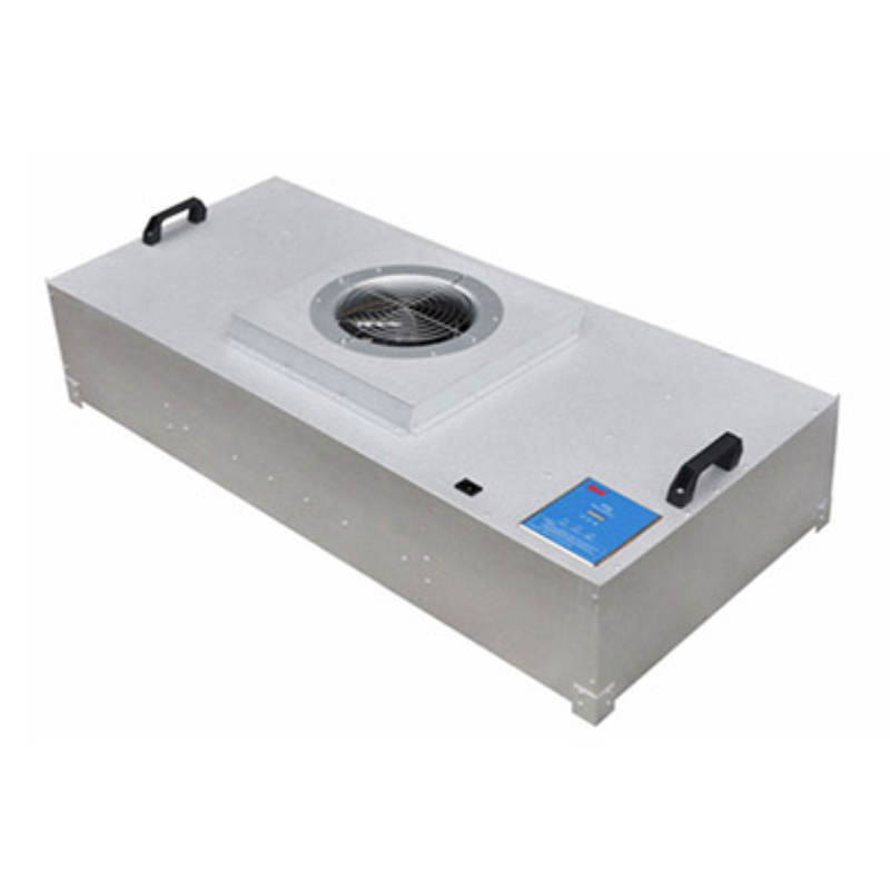
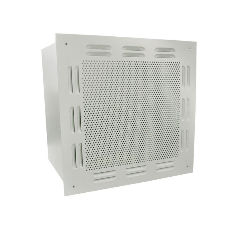
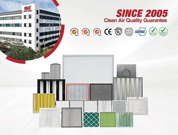
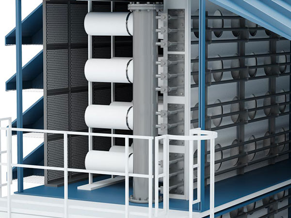
It widely used to hospital operation room, laboratory, pharmaceutical room, electronics, optical fiber equipment and food processing factory etc.
About Us
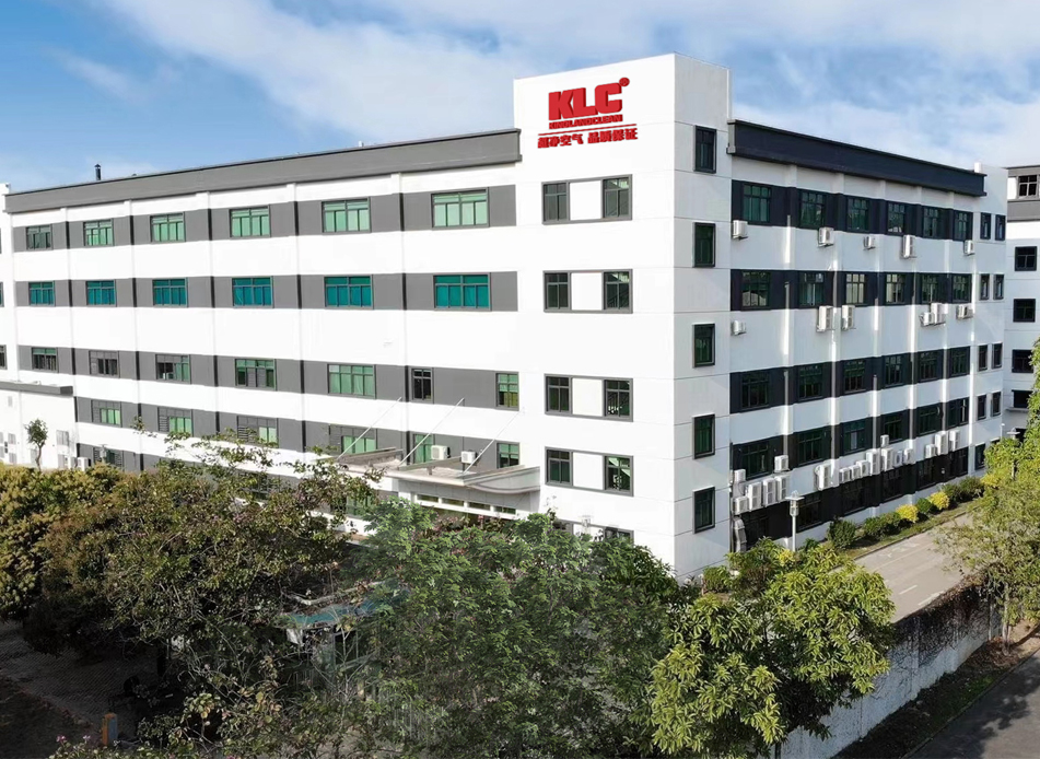
GUANGZHOU KLC CLEANTECH CO., LTD., as a leading supplier of air filters and cleanroom equipment, is committed to providing excellent solutions for clean and fresh air.

28+

YEARS OF EXPERIENCE

  Hong Kong Kingland Investment Limited has been committed to advancing air purification technology and delivering exceptional products and services to customers worldwide since its inception. Leveraging Hong Kong's strategic position as an international financial and commercial center, we are able to efficiently integrate global resources, expand into international markets, and establish close partnerships around the world.   Since 1994 when KLC was built, we have been dedicated to the research and development of air purification products. We have invested a large amount of funding and technology to ensure that our customers can enjoy the latest high-quality products and the most professional additional services. Since the 21st century, KLC has expanded its reach to every corner of the world, accumulating extensive experience and application knowledge in order to provide more comprehensive products and services. KLC was the first enterprise in the purifying field to pass the ISO14001 and ISO9001 certifications. We possess top-ranking clean workshops and production lines, as well as advanced air filter equipment. As one of the leading manufacturers in researching, designing, and producing products related to clean rooms, our products and production technologies have obtained dozens of national patents. Now, we have garnered support from many leading enterprises across various fields and countries. With our "Globalization thinking" business philosophy, KLC products are spreading throughout Asia, Europe, and America. No matter where you are, we are always by your side.   In Mainland China, we have established an advanced production base that focuses on the research, development, production, and sales of air purification products. This production base is an integral part of our global layout, ensuring that we can continue to deliver high-quality products and services to customers worldwide.   THE HISTORY OF KLC 2005﹎﹎﹎At the beginning of establishment, KLC committed to the construction projects in the area of air conditioning, refrigeration, ventilation, air treatment, dust-free workshop, etc, focusing on China's emerging markets for future high-tech manufacturing industry, which has provided a solid foundation for industrial clean room area in technology, management and services. 2006﹎﹎﹎KLC registered our own trademarks, transferred air purification manufacturing market from scattered hand-made workshop to factory integration production. In the same year, KLC became China's first batch company in the air purification field to pass the SGS ISO9001 and SGS ISO14001 certification, these criteria for quality and environment management have built a solid basic for KLC's management and development. KLC also won the "National Quality Credit Enterprise" in 2006. 2007﹎﹎﹎KLC sales channel developed into diversified stage, began foreign trade, undertook a large number of overseas orders, reached cooperation with numbers of well-known domestic and foreign enterprises. In the same year, KLC products quality reached to a higher level, highly praised by domestic and foreign partners, and won the " Enterprise of Good Creditworthiness " award. 2009﹎﹎﹎KLC' worked with more than 3,000 end-users, and established one of few 10,000 clean class clean room for HEPA filters and ULPA filter manufacturing, in order to ensure the filters are free from pollution before customer receive the products. The clean room has effectively meet the requirement for business and future expansion of capacity, logistics or hardware equipment. 2011﹎﹎﹎KLC again researched and developed our own a variety of purification products, the world-class quality, appearance and utility model patents has set off a clean air whirlwind among the industry. Opened up a new situation in the domestic air purification industry. 2013﹎﹎﹎KLC product technology break through the traditional constraints successfully, innovation and improvement has been promoted, some product projects have been reviewed and passed the state-level scientific and technological innovation projects. In the same year, KLC is awarded as "high-tech" enterprises. 2014﹎﹎﹎KLC imported a large-scale media folding machine and flat foaming machine, became the first in southern China producing 1500mm width mini-pleat media filter. 2016﹎﹎﹎KLC invested huge sums of money to introduce an U-level testing equipment for filter's air flow, resistance and efficiency testing, filling the blank in southern China market of air filter testing, secondary testing equipment with the Chinese Academy of Sciences. KLC all products start to label with a style code, which enable the immediate tracing from production, logistics and product maintenance. 2017﹎﹎﹎KLC brand get a further upgrade, integrated comprehensively both from internal and external, including APP, suppliers, supply chain, logistics system etc. Starting a new journey from the state-own company Da An Gene become a shareholder of KLC. 2020﹎﹎﹎Introducing fully automatic MPPS filtration efficiency scanning equipment and air flow resistance detection equipment imported from the United States to enhance KLC's product development capabilities and meet higher customer demands.. 2022﹎﹎﹎KLC was awarded the title of "Specialized, Refined, Unique and New" enterprise and innovative small and medium-sized enterprise. In the same year, KLC's R&D center was approved as the Guangdong Engineering R&D Center. 2024﹎﹎﹎Introducing fully automatic MPPS filtration efficiency scanning equipment and air flow resistance detection equipment imported from the United States to enhance KLC's product development capabilities and meet higher customer demands.
Production
Automatic Sealant Glue Inject Machine Interactive laser cutting machine Automatic Digital Punching Machine Automatic Digital Bending Machine Automatic Folding Machine Combination Folding Machine Hepa Media Pleating Machine Semi-Automatic Sealant Glue Inject Machine2 Separator Filter Aluminum Foil Presing Machine Efficiency, Air Flow, Resistance Testing Machine PAO Testing Equipment PAO Testing Equipment2 Smoke Leakage Test Air Duct Type Particle Counter Testing Efficiency, Air Flow, Resistance Testing Machine 2 Semi-Automatic Sealant Glue Inject Machine    
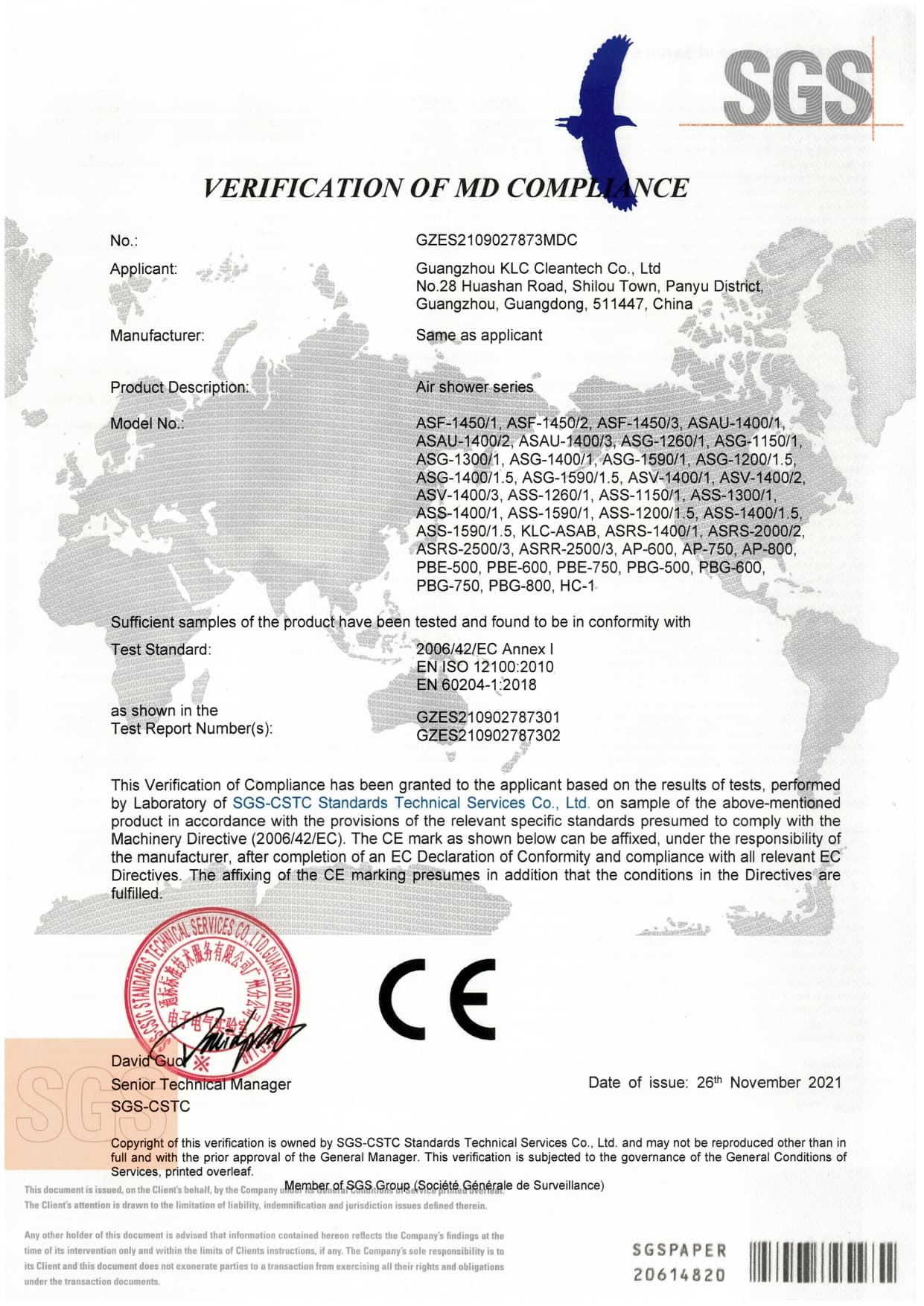
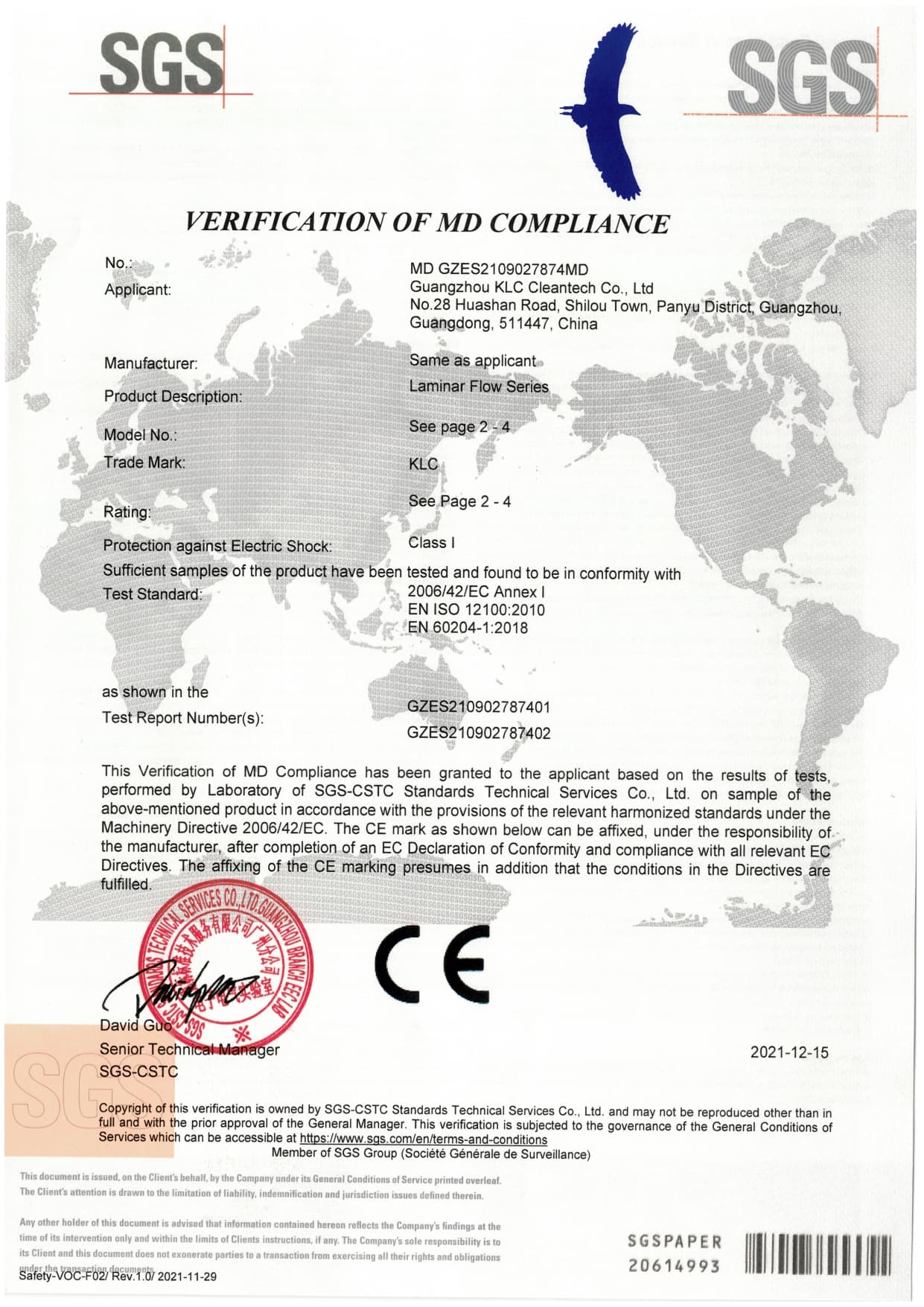
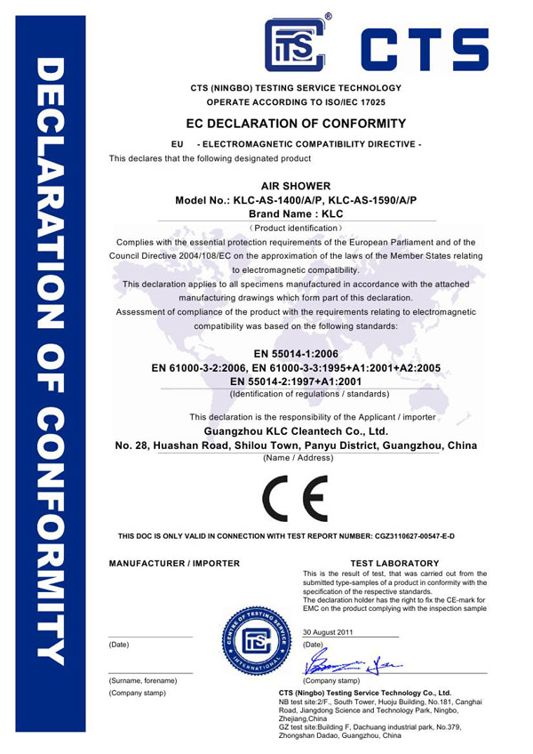
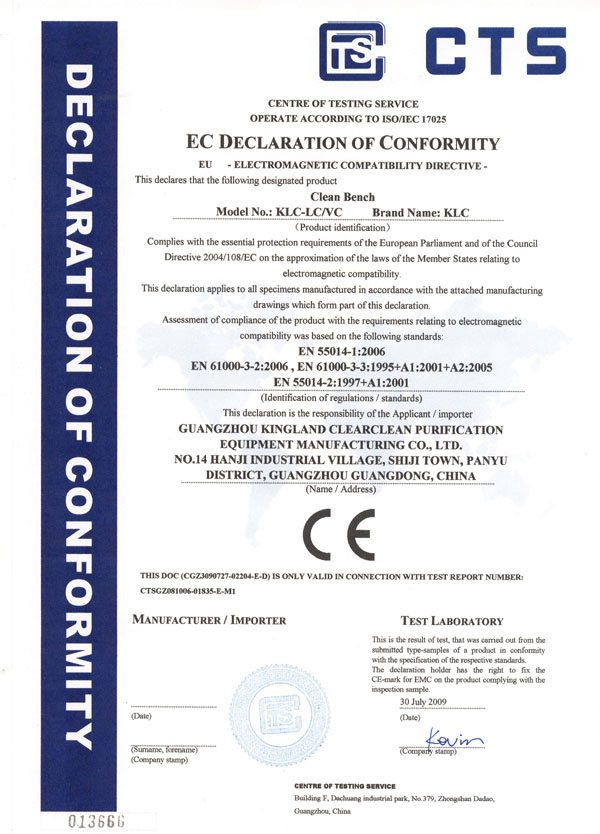
Certificate
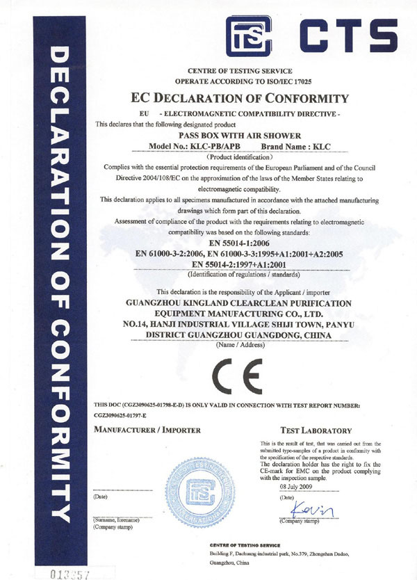
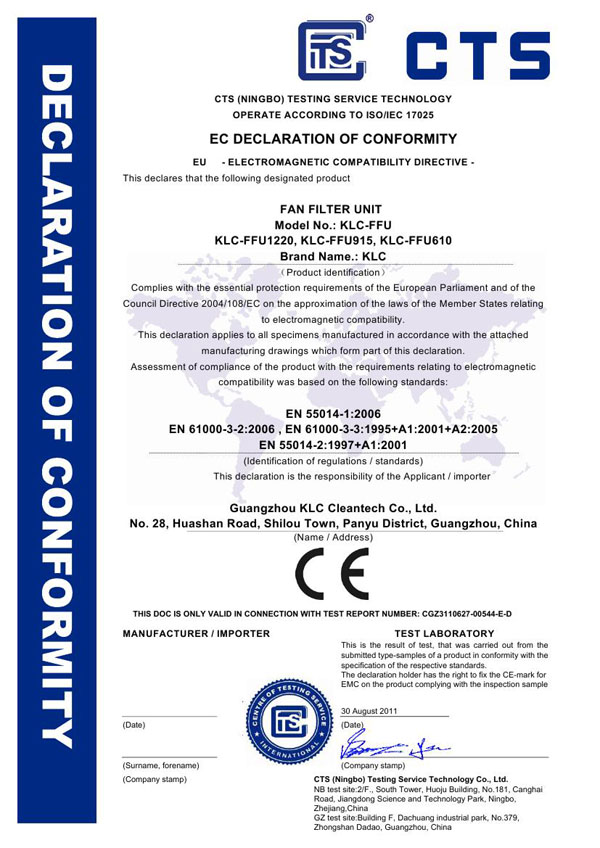
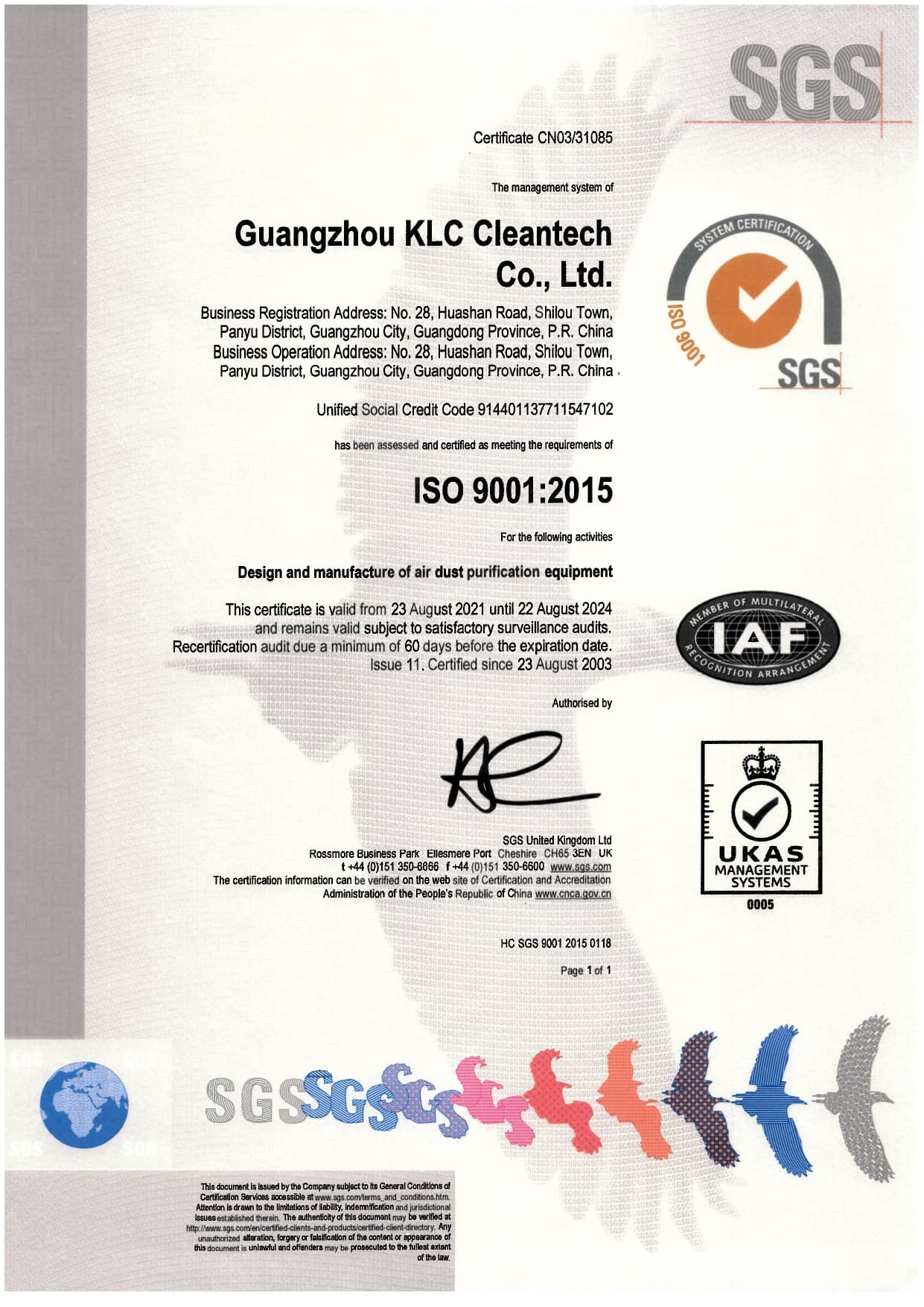
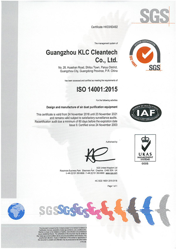
6S management; ISO9001 quality management system; ISO14001 environmental management system
  • CE-AS Series
  • CE-LF Series
  • Air shower-CE
  • CE-Clean bench
  • CE-Pass box
  • FFU-CE
  • ISO9001 (EN)
  • ISO14001 2015
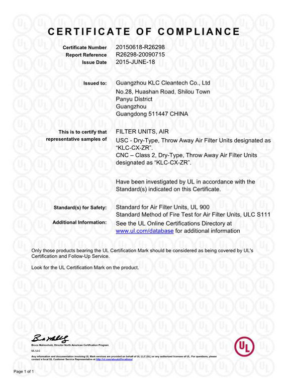
  • Pleated Filter-UL-Certificate of Compliance
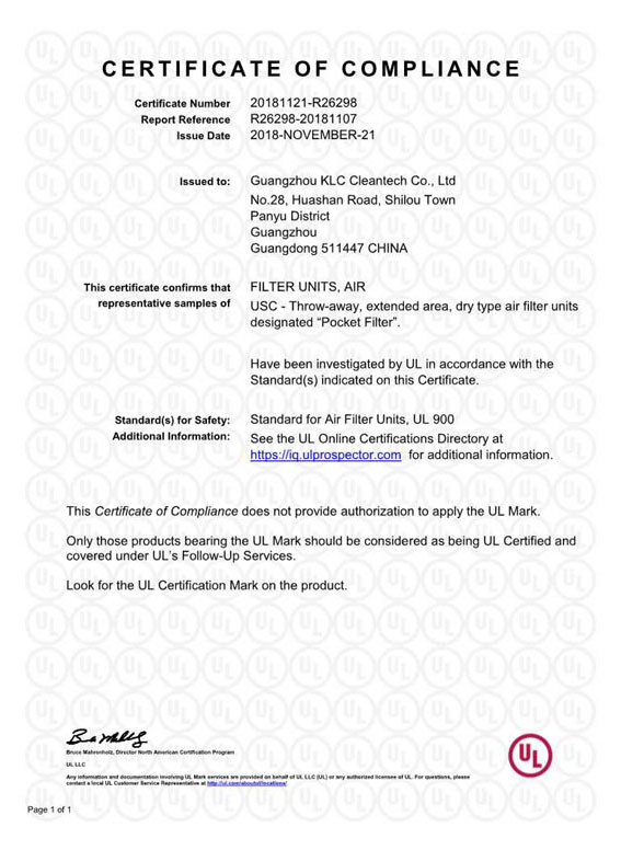
  • Pocket Filter-UL-Certificate of Compliance
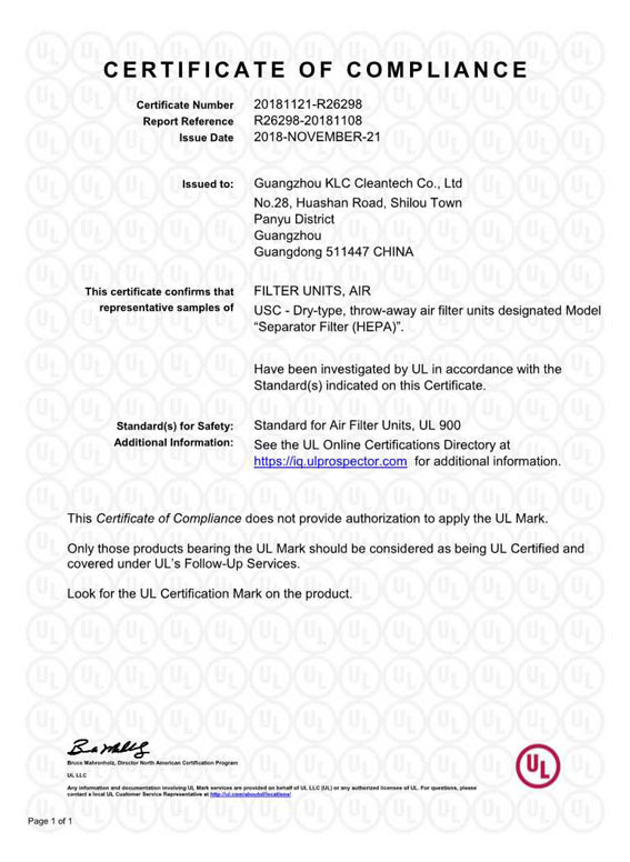
  • Separator Filter-UL-Certificate of Compliance
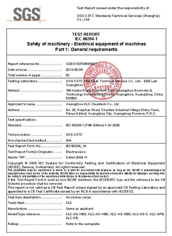
  • SGS AIR Shower test report
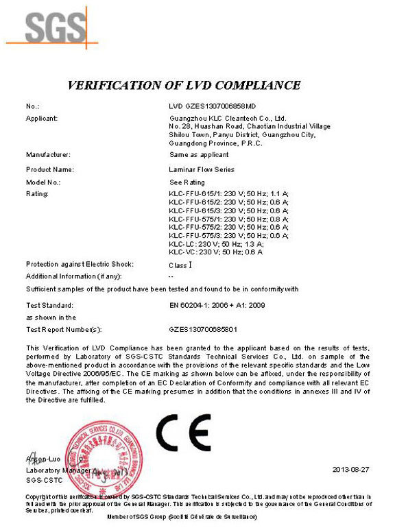
  • SGS FFU & LC VC
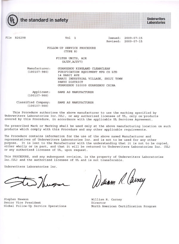
  • 2009 UL-filter
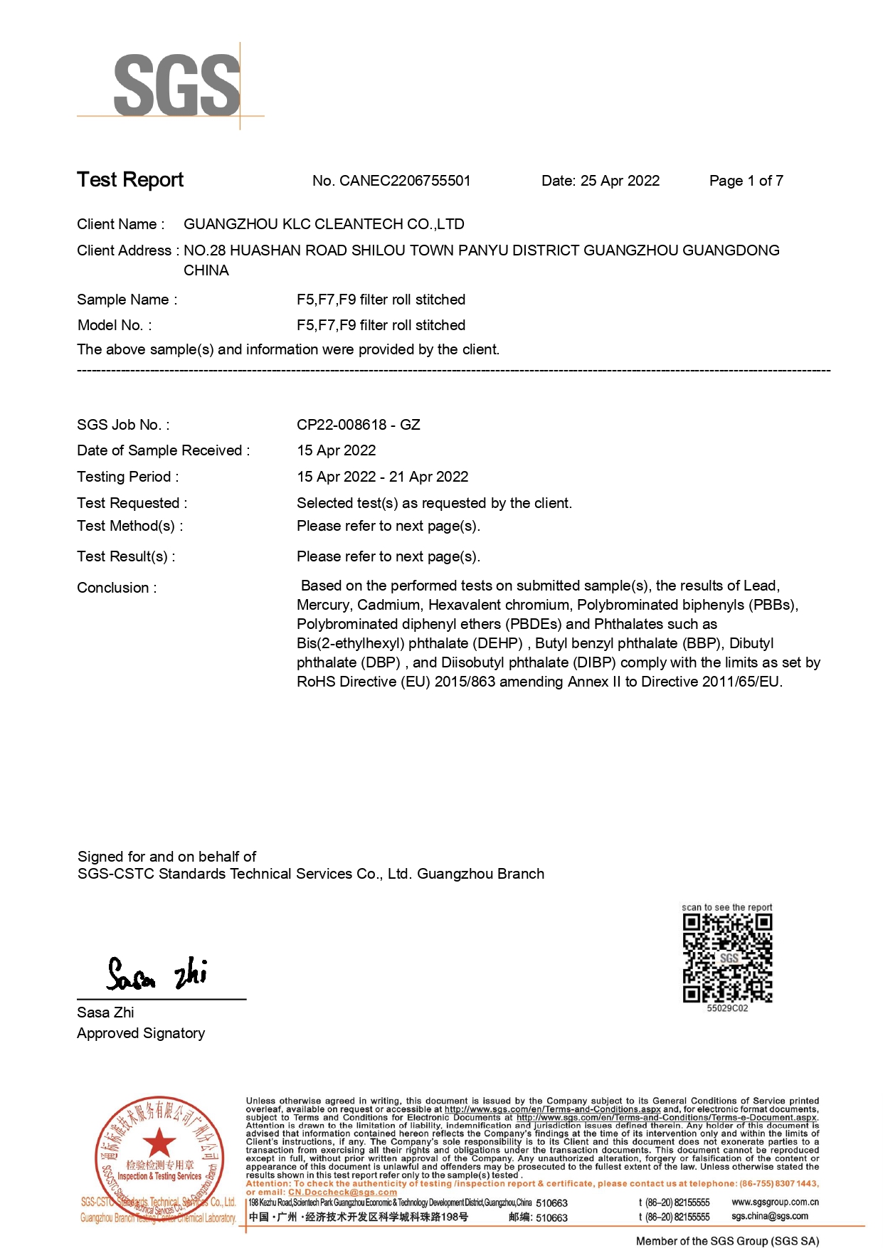
  • SGS F5 F7 F9 filter roll stitched RoHS
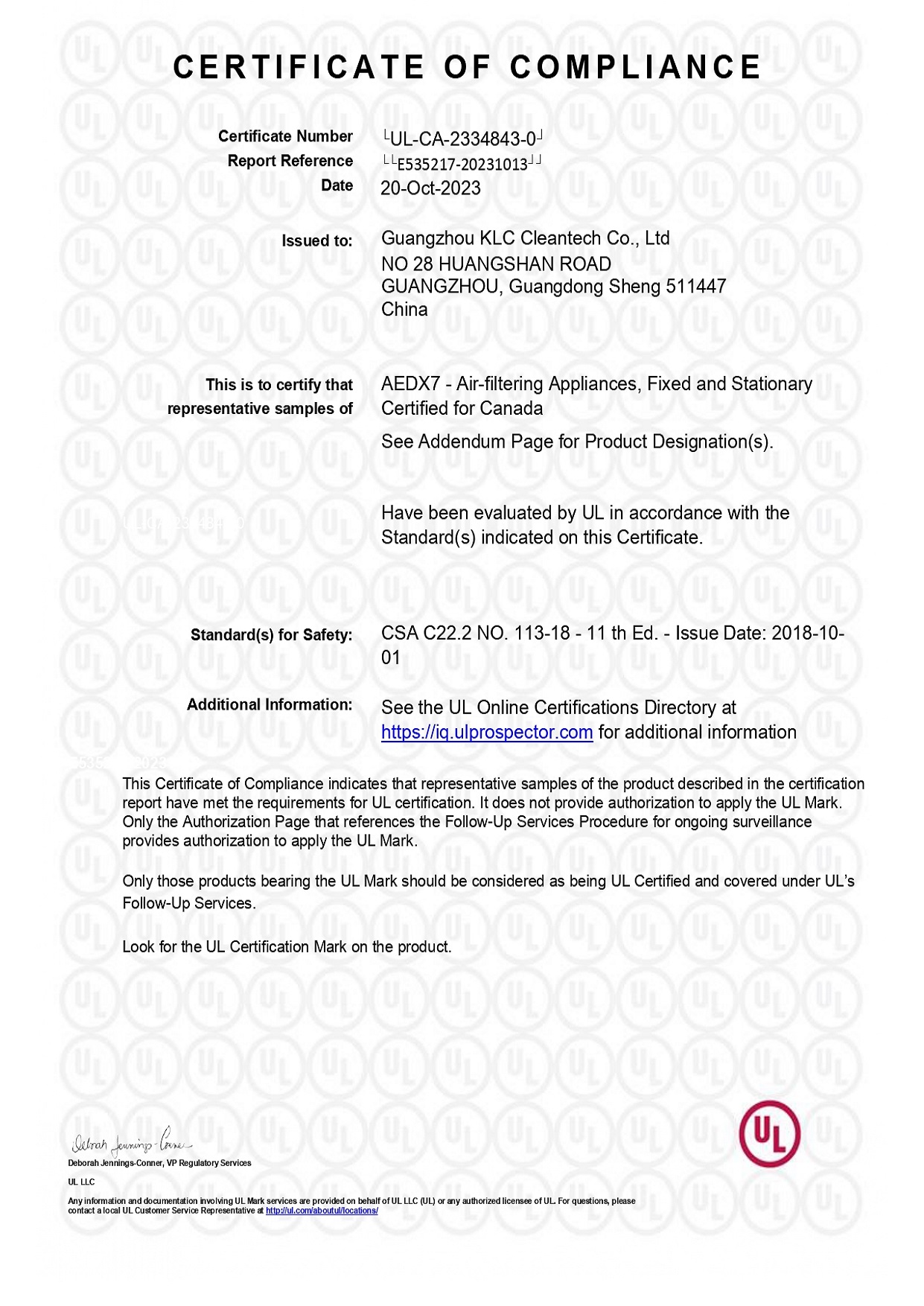
  • Certificate ffu ul
Our Team
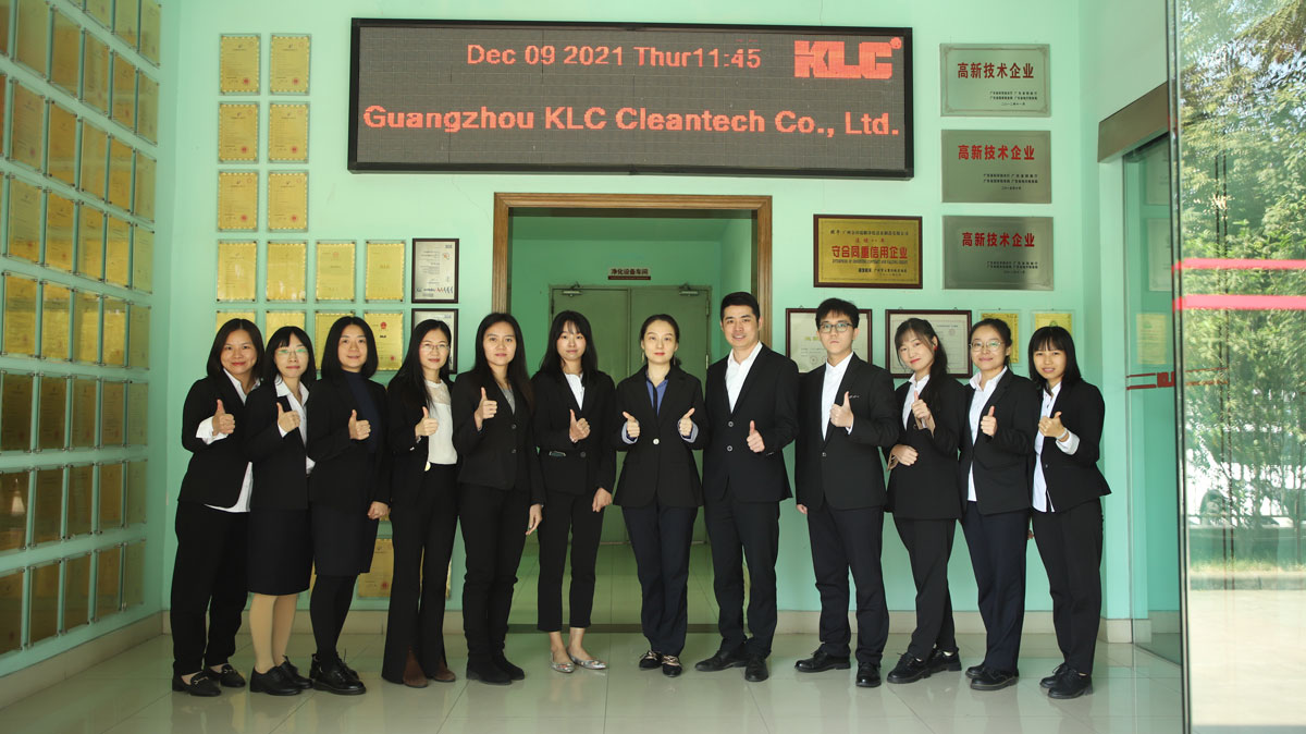
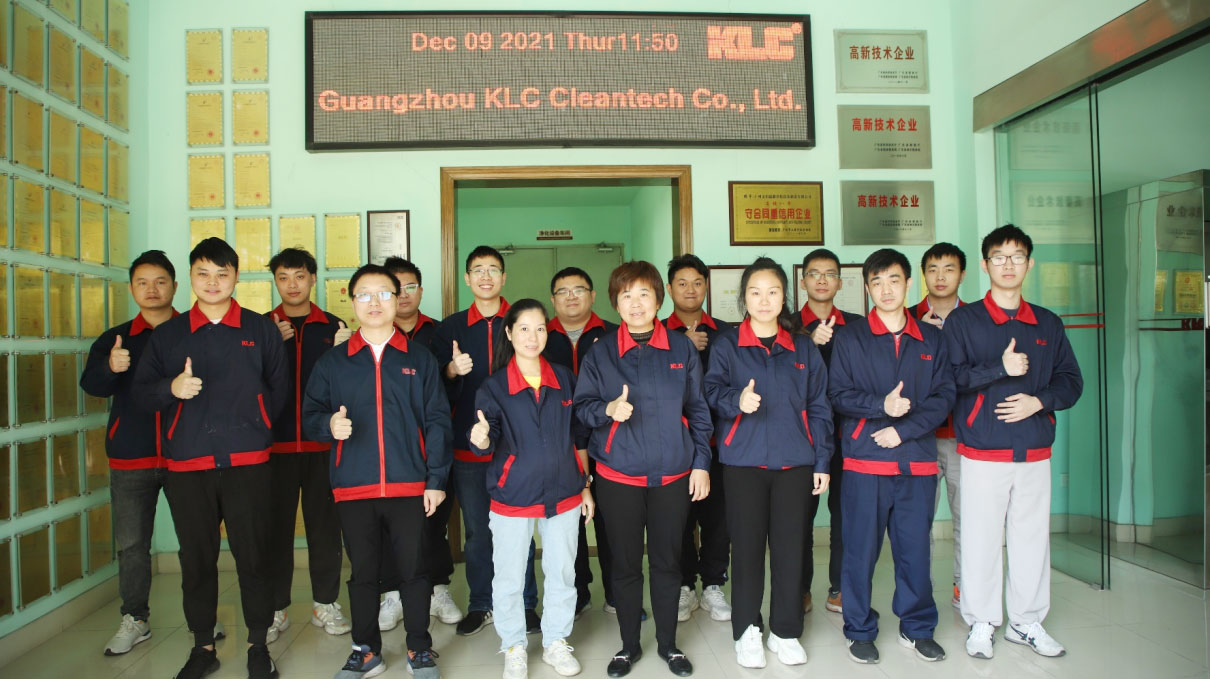
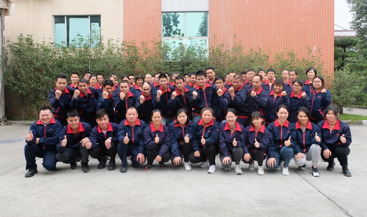
Senior & professional sales service team and Professional production team
  • Senior & professional sales service team
    Senior & professional sales service team

    More than 10 years experience in filter and clean room equipment sales

  • Senior design and development team
    Senior design and development team

    More than 10 years of experience

  • Professional production team
    Professional production team

    6S management

  • 1994
    0
    Since
  • 2000
    0+
    Sales
  • 500
    0+
    Solutions
  • 100+
    0
    Countries
About Us
GUANGZHOU KLC CLEANTECH CO., LTD., as a leading supplier of air filters and cleanroom equipment, is committed to providing excellent solutions for clean and fresh air.
Featured Products
The products involve 58 fields and have a certain market share.
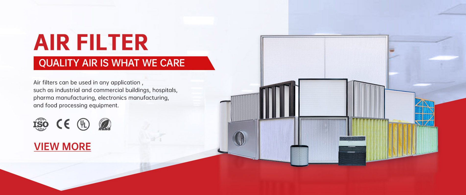
  • Air Filter
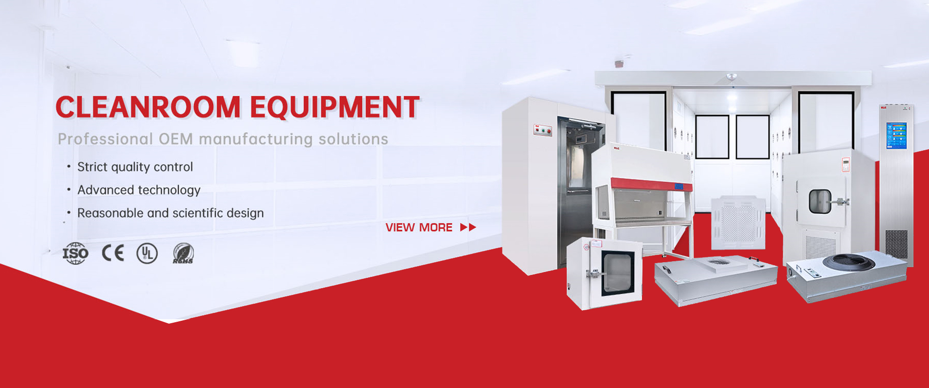
  • Cleanroom Equipment
Certificate
6S management; ISO9001 quality management system; ISO14001 environmental management system
  • CE-AS Series

    CE-AS Series

  • CE-LF Series

    CE-LF Series

  • Air shower-CE

    Air shower-CE

  • CE-Clean bench

    CE-Clean bench

  • CE-Pass box

    CE-Pass box

  • FFU-CE

    FFU-CE

  • ISO9001 (EN)

    ISO9001 (EN)

  • ISO14001 2015

    ISO14001 2015

  • Pleated Filter-UL-Certificate of Compliance

    Pleated Filter-UL-Certificate of Compliance

  • Pocket Filter-UL-Certificate of Compliance

    Pocket Filter-UL-Certificate of Compliance

  • Separator Filter-UL-Certificate of Compliance

    Separator Filter-UL-Certificate of Compliance

  • SGS AIR Shower test report

    SGS AIR Shower test report

  • SGS FFU & LC VC

    SGS FFU & LC VC

  • 2009 UL-filter

    2009 UL-filter

  • SGS F5 F7 F9 filter roll stitched RoHS

    SGS F5 F7 F9 filter roll stitched RoHS

  • Certificate ffu ul

    Certificate ffu ul

Latest News
KLC provides long-term security and technical support, based on data and facts, comprehensive and in-depth analysis, to provide you with professional advice and detailed product descriptions.
  • Semiconductor Cleanroom Setup Guide: ISO 3 to ISO 6 Equipment Requirements and FFU Coverage Calculation
    Jul 14, 2026
    Semiconductor Cleanroom Setup Guide: ISO 3 to ISO 6 Equipment Requirements and FFU Coverage Calculation
    Setting up a semiconductor cleanroom from ISO 3 to ISO 6 requires precise layout design, where ceiling FFU coverage must reach 85% to 100% for ISO 3, 60% to 80% for ISO 4, and 30% to 50% for ISO 5, satisfying air change rates and laminar airflow uniformity. This technical guide covers the engineering design and HVAC calculations necessary for semiconductor fabrication plants (fabs). It details the ISO cleanliness requirements for photolithography, etching, and packaging, explains the mathematical formula for Fan Filter Unit (FFU) ceiling coverage, and addresses the critical challenges of vibration, noise, and airflow uniformity. This guide is written for fab facility engineers, process designers, and cleanroom HVAC consultants who need to build or optimize ultra-clean microelectronics production facilities.      Process-Specific ISO Class Cleanliness Requirements  Semiconductor manufacturing is one of the most environmentally sensitive industrial processes. As transistor gate widths shrink to sub-nanometer scales, even a single sub-micron particle can bridge circuit lines on a silicon wafer, rendering an entire microchip defective. Consequently, semiconductor fabs are divided into multiple, highly controlled zones depending on the sensitivity of the specific process: Photolithography (The “Yellow Room”): This is the heart of the fab, where circuit patterns are projected onto silicon wafers. Due to the extreme vulnerability of this step, photolithography zones must meet ISO Class 3 or ISO Class 4 standards. These zones require strict yellow lighting (to prevent premature exposure of photoresist chemicals) and absolute control over airborne molecular contamination (AMCs) and VOCs in addition to particulate control. Etching and Chemical Vapor Deposition (CVD): The process of removing material and depositing thin chemical films on the wafer requires ISO Class 4 or ISO Class 5 cleanliness. Particulates here could block etching gases or become embedded within the molecular layers of the semiconductor. Assembly, Packaging, and Testing (Back-End): Once the wafers are cut into individual dies, they are encapsulated in protective housings. This back-end stage is less vulnerable to sub-micron particles, and is typically housed in ISO Class 5 or ISO Class 6 cleanrooms.    Sample Calculation: ISO Class 5 Cleanroom  Target ISO Class Typical Semiconductor Process FFU Ceiling Coverage Filter Grade (EN 1822) Recommended ACH Airflow Type ISO Class 3 Photolithography (Advanced node exposure core) 85% to 100% U15 to U16 ULPA 360 to 600+ Unidirectional / Laminar ISO Class 4 Advanced Wet Etching, Ion Implantation 60% to 85% U15 ULPA 300 to 540 Unidirectional / Laminar ISO Class 5 CVD, Epitaxial Deposition, Back-end Dicing 30% to 60% H14 HEPA to U15 240 to 480 Unidirectional / Laminar ISO Class 6 IC Packaging, Testing, Photomask Storage 15% to 30% H14 HEPA 60 to 120 Non-Unidirectional      Micro-Vibration and Acoustic Control Requirements  In semiconductor manufacturing, mechanical vibration is a critical concern. Photolithography machines use high-precision lenses and lasers to etch circuits with nanometer-level tolerances. Vibrations from ceiling-mounted FFU motors can easily transmit through the ceiling grid down to the structural pillars and floor, causing image blur during wafer exposure. To prevent micro-vibration issues, semiconductor fabs must implement several engineering safeguards: 1. Structural Isolation: The cleanroom ceiling grid must be structurally isolated from the building’s primary concrete frame. FFUs should be suspended from a secondary structural steel grid that is completely separate from the support structure of the lithography equipment. 2. Dynamic Balancing: Every FFU fan and impeller must undergo high-precision dynamic balancing. The balance grade should conform to ISO 1940 G2.5 standards, which limits residual unbalance to prevent micro-vibrations. 3. Low-Vibration Motors: Brushless EC motors should be selected. These motors run more smoothly and produce significantly less vibration than traditional AC induction motors, which suffer from electromagnetic slip and physical rotor wear.    Airflow Uniformity and Velocity Control  In semiconductor cleanrooms, maintaining laminar (unidirectional) airflow is essential. The downward velocity must be uniform across the entire ceiling area to prevent turbulences, which can trap particles and cause them to settle on exposed silicon wafers. - Airflow Velocity Standard: For ISO Class 3 to 5, the nominal downflow velocity must be maintained at 0.45 m/s (90 fpm). - Airflow Uniformity Limit: The maximum allowable variation in downflow velocity across the ceiling is ±20% (0.36 to 0.54 m/s). Any larger variance can create localized pressure differentials, leading to recirculating eddies that keep dust particles suspended over the process equipment.    KLC EC Motor FFU Systems for Semiconductor Fabs  KLC International manufactures high-performance Fan Filter Units specifically engineered for the demanding environments of modern semiconductor fabs. Our systems are designed with several key technical features: • Low Noise Profile: KLC FFUs utilize aerodynamically optimized impellers and integrated acoustic chambers to maintain noise levels below 53 dB(A) at a nominal velocity of 0.45 m/s, which is critical for operator comfort in large fabs containing thousands of units. • Precision Vibration Control: Every KLC semiconductor-grade FFU is equipped with dynamically balanced aluminum alloy impellers certified to ISO 1940 G2.5 standards, ensuring zero micro-vibrations are transmitted to delicate lithography tools. • Ultra-Efficient EC Technology: KLC FFUs utilize high-efficiency EC motors that achieve up to 88% motor efficiency, reducing heat generation and power consumption across the fab’s HVAC system. • RS485 Group Control System: Fabs can coordinate and monitor over 10,000 FFUs from a central control room. The system supports Modbus/RS485 protocol, allowing real-time monitoring of motor speed, pressure drops, and electrical faults, with automated speed compensation for filter loading.      FAQ: Semiconductor Cleanroom Design  Why is FFU coverage of 85% to 100% required for ISO Class 3 cleanrooms? An ISO Class 3 cleanroom requires near-complete FFU coverage to maintain strict, vertical unidirectional laminar airflow. At 85% to 100% coverage, the ceiling becomes a continuous membrane of ULPA filters, which ensures that air moves downward in a uniform piston-like manner. This constant downward flow sweeps any particles away from sensitive lithography areas instantly, preventing them from drifting laterally. What is the difference between H14 HEPA and U15 ULPA filters in semiconductor fabs? An H14 HEPA filter has an efficiency of ≥99.995% for particles of 0.3 microns. A U15 ULPA (Ultra-Low Penetration Air) filter provides an efficiency of ≥99.9995% at the Most Penetrating Particle Size (MPPS), which is typically between 0.12 and 0.17 microns. In advanced semiconductor fabs where particles as small as 0.1 microns can cause chip failure, U15 or U16 ULPA filters are required for front-end lithography and diffusion zones. How does VOC contamination affect semiconductor wafers, and how is it controlled? Volatile Organic Compounds (VOCs) and Airborne Molecular Contaminants (AMCs) can chemically react with silicon wafers or condense onto optical lenses in lithography tools, causing haze and defects. To control this, semiconductor-grade FFUs are often equipped with a dual-stage filtration system: an active carbon or chemical dry-scrubbing filter layer upstream of the ULPA filter to capture organic gases, acids, and bases. What is the ideal humidity level in a semiconductor cleanroom and why? The standard humidity target is 45% RH ± 5%. If the humidity falls below 40% RH, static electricity can build up, causing electrostatic discharge (ESD) that can destroy microchip circuits or attract dust particles to the wafers. If humidity exceeds 50% RH, water vapor can condense onto chemical photoresists, causing adhesion failures and promoting the corrosion of metal circuit layers. How do engineers balance the airflow in a fab cleanroom containing thousands of FFU? Manually balancing thousands of individual units is impossible. Engineers use digital group control systems connected to EC motor FFUs. The control system communicates via RS485 or Ethernet, allowing technicians to enter the target air velocity for different zones. The system then automatically adjusts each FFU’s speed and monitors pressure sensors to maintain uniform, balanced airflow across the entire fab. What is the role of the raised access floor in semiconductor cleanrooms? A raised access floor with perforated tiles is crucial for maintaining laminar airflow. The downward airflow from the ceiling-mounted FFUs passes through these perforated tiles into the sub-floor plenum, where it is drawn back up through side-wall return shafts to the ceiling plenum. This prevents the air from hitting a solid floor and creating turbulent recirculations that would trap particles in the working zone. Why are brushless EC motors preferred over AC motors in semiconductor cleanrooms? EC motors use electronic commutation instead of physical brushes, eliminating mechanical wear and carbon dust generation. They also run much cooler, which reduces the thermal load on the cleanroom’s cooling systems, and they can be modulated with extreme precision from 0% to 100% speed, allowing the group control system to maintain exact airflow velocities. How do KLC FFUs minimize structural vibration? KLC FFUs utilize a combination of dynamically balanced impellers, lightweight aluminum fan housings, and internal rubber vibration isolators that decouple the motor assembly from the FFU casing. This ensures that any residual micro-vibrations generated by the motor are absorbed within the unit, preventing them from being transmitted to the ceiling grid or cleanroom walls. Conclusion and Recommendation Designing a semiconductor cleanroom requires a precise balance of high-efficiency filtration, uniform airflow, and rigorous vibration control. To ensure your fab meets strict ISO 3 to ISO 6 standards without compromising process yields, work with a manufacturer that can provide high-efficiency EC motor FFUs with integrated group control systems. For high-performance, low-vibration, and energy-efficient semiconductor cleanroom equipment, explore the complete product range from KLC International. Visit KLC International to review technical specifications, download FFU CAD drawings, and consult with our microelectronics application engineering team.
  • Fan Filter Unit vs HEPA Filter Box: Which Terminal Filtration Solution Is Right for Your Cleanroom?
    Jul 09, 2026
    Fan Filter Unit vs HEPA Filter Box: Which Terminal Filtration Solution Is Right for Your Cleanroom?
    The choice between Fan Filter Units (FFU) and HEPA Filter Boxes depends on air handling architecture: active FFUs utilize integrated motors to draw and recirculate air locally, while passive HEPA boxes rely on central Air Handling Units (AHU) and extensive ducting to deliver conditioned air to terminal filters. This technical article covers the mechanical principles, operational characteristics, and installation complexities of active Fan Filter Units (FFUs) versus passive HEPA Filter Boxes (HEPA boxes). We analyze their impact on HVAC design, compare their lifecycle costs, and present a structured engineering selection matrix. This guide is written for cleanroom architects, mechanical consultants, and facilities managers across the semiconductor, pharmaceutical, and healthcare sectors who must choose the optimal terminal filtration system for new cleanroom builds or facility retrofits.    Technical Principles: Active vs. Passive Cleanroom Ventilation  Terminal filtration is the final barrier between a cleanroom’s air supply system and its controlled environment. Deciding how to deliver and filter this air dictates the overall layout, structural load, and energy footprint of the facility’s HVAC infrastructure.    Fan Filter Unit (Active Filtration)  A Fan Filter Unit (FFU) is an active, self-contained terminal filtration module. It consists of a motorized impeller (fan) mounted directly on top of a HEPA or ULPA filter housing. - Mechanism of Operation: The integrated fan draws air from a ceiling plenum (often a recirculating plenum) or a low-pressure duct. It pressurizes the air inside the unit’s internal mini-plenum and forces it downward through the HEPA filter media. - System Impact: Because each FFU has its own drive mechanism, the external air handling system (AHU) does not need to overcome the static pressure drop of the HEPA filter. The AHU is only responsible for introducing fresh makeup air, controlling temperature and humidity, and delivering pre-conditioned air to the ceiling plenum.      HEPA Filter Box (Passive Filtration)   A HEPA Filter Box (also known as a terminal diffuser or terminal HEPA housing) is a passive device. It does not contain any motorized components. - Mechanism of Operation: The HEPA box receives pre-conditioned and highly pressurized air from a central AHU via a branching network of galvanized or insulated flexible ducts. The air is forced through the box’s terminal HEPA filter by the static pressure generated by the central AHU’s massive supply fan. - System Impact: The central AHU must generate sufficient static pressure to overcome the cumulative resistance of all dampers, elbows, long duct runs, and the terminal HEPA filter itself. This requires large central fan motors and extensive, balancing-intensive ductwork.      Engineering Comparison and Selection Matrix  The choice between active and passive terminal filtration impacts every aspect of cleanroom operation, from acoustic comfort to long-term flexibility.    Ceiling Space and Structural Load  FFUs are heavier than passive HEPA boxes because of their integrated motors and impellers. Consequently, the ceiling grid (T-bar or heavy-duty FFU grid) must be engineered to support this additional static weight. However, FFUs require far less vertical ceiling space because they draw air directly from an open ceiling plenum. HEPA boxes, while lighter, require substantial vertical clearance in the ceiling void to accommodate branching duct runs and manual volume control dampers.    Noise and Vibration Control  Because FFUs contain individual motors, having hundreds of units in a large cleanroom can introduce localized noise and vibration. This is a critical concern in sub-micron semiconductor fabs (where photolithography equipment is sensitive to micro-vibrations) or research laboratories. Modern FFU designs address this by using precision-balanced motorized impellers and vibration-dampening mountings. Passive HEPA boxes generate zero localized vibration because they have no moving parts. However, high-velocity air flowing through duct elbows and dampers in passive systems can generate high-frequency acoustic noise if not insulated correctly.    Air Balancing and Control  Balancing a cleanroom with passive HEPA boxes requires manual adjustment of volume dampers inside the ceiling plenum, which is a tedious, iterative process. If one HEPA box damper is adjusted, the pressure shifts, affecting airflow in all other boxes. FFUs, especially when equipped with electronically commutated (EC) motors, can be integrated into a digital group control system (using RS485 or Modbus). Technicians can adjust the air velocity of individual units or groups from a central computer, and the motors can automatically adjust their speed to maintain uniform airflow as the filters load.   Operational & Technical Parameter Fan Filter Unit (FFU) - Active HEPA Filter Box - Passive Drive Mechanism Integrated motor & impeller (Active). None; relies on central AHU fan (Passive). Air Supply Method Draws from recirculating ceiling plenum or low-pressure duct. Fed by high-pressure ducted branch lines. Ceiling Structural Load High (~20 to 35 kg per 4x2 unit). Low (~8 to 15 kg per unit). Ducting Requirement Minimal (often none, if using a return air plenum). High (extensive branching duct network). Airflow Balancing Digital/automated via EC motor group control. Manual adjustment of volume control dampers. Ceiling Height Requirement Low (draws from open plenum; thin profiles available). High (needs space for duct bends and dampers). Localized Noise Level 52 to 58 dB(A) per unit (cumulative in large arrays). Extremely low (limited to air exit duct noise). Vibration Characteristics Low, localized micro-vibration (motor balance critical). Zero equipment-related vibration. Initial Capital Investment High (due to hundreds of motorized units and controllers). Moderate (lower unit cost, offset by ducting costs). Operational Flexibility Extremely high (modular plug-and-play; scalable). Low (requires re-ducting and re-balancing to scale).     The installation workflows for active and passive systems differ significantly: • FFU Installation: FFU systems are highly modular. Units are lifted into the ceiling grid from the room side or plenum side and plugged into a localized power rail. Since there are minimal or no duct connections, physical installation is fast. During commissioning, air velocity is adjusted digitally. • HEPA Box Installation: Installing passive HEPA boxes is labor-intensive. Each box must be hung from the building’s structural slab using threaded rods, and then connected to the main supply duct using flexible or rigid collars. Airflow balancing requires technicians to climb up and manually adjust dampers while taking air velocity measurements with a hood, which can take days or weeks for large cleanrooms.    Lifecycle and Maintenance Cost Analysis  Evaluating the true cost of terminal filtration requires analyzing both initial capital expenditure (CAPEX) and ongoing operational expenditure (OPEX). • CAPEX Considerations: Passive HEPA boxes have a lower initial unit price than FFUs. However, when the cost of extensive insulated ducting, volume control dampers, and the larger horsepower motors required for the central AHU is factored in, the capital cost gap between the two systems shrinks considerably. • OPEX Considerations: FFUs equipped with energy-efficient EC motors can lower operational costs. Because the ceiling plenum acts as a low-resistance path, the total static pressure that the HVAC system must overcome is dramatically reduced, translating to lower overall fan energy consumption. • Maintenance Effort: Passive HEPA boxes require minimal maintenance, as there are no mechanical parts to fail; only the HEPA filter must be replaced. FFUs require periodic inspection of the motors, though modern brushless EC motors have a bearing life exceeding 50,000 to 100,000 hours of continuous operation.   Cost & Operational Category Fan Filter Unit (FFU) HEPA Filter Box (Passive) Filter Replacement Labor Low to moderate (easy to swap from room side). Low to moderate (easy to swap from room side). Motor & Fan Maintenance Periodic motor inspection/replacement (long bearing life). Zero terminal maintenance; only central AHU maintenance. System Energy Efficiency High (EC motors run at optimal efficiency; low duct losses). Low to moderate (high static pressure losses in ductwork). Duct Cleaning & Inspection Negligible (open ceiling plenum system). High (requires periodic inspection of branching ducts). Facility Modification Cost Extremely low (simply add or relocate modules in grid). High (requires re-engineering ducts and balancing).    Hybrid Cleanroom Configurations: When to Combine Both  In modern cleanroom design, engineers do not always treat FFU and HEPA boxes as mutually exclusive. Hybrid configurations are frequently used to optimize performance and budget: Class-in-Class Layouts: In a large ISO Class 7 pharmaceutical packaging hall, specific zones (like the filling line or open-container handling areas) must meet ISO Class 5 standards. Rather than upgrading the entire room to FFU filtration, designers install passive HEPA boxes for the general ISO Class 7 area and suspend an array of active FFUs directly over the critical filling line to create a localized ISO 5 laminar flow zone. Plenum Pressurization Hybrid: In some cleanrooms, a central AHU is used to supply pre-conditioned air to a sealed ceiling plenum, maintaining it under a slight positive pressure. Active FFUs then draw from this pressurized plenum and filter the air into the room. This reduces the motor load on the FFUs and ensures absolute uniform downflow.    KLC International’s Versatile Terminal Filtration Systems  KLC International offers high-quality solutions for both active and passive cleanroom terminal filtration, allowing engineers to choose the best configuration for their application. • KLC Fan Filter Units (FFU): KLC FFUs feature high-performance brushless EC motors that deliver up to 50% energy savings compared to standard AC units. They operate at low noise levels (≤53 dB(A) for standard models) and are equipped with RS485 group control capabilities, allowing a single terminal to manage up to 7,900 units. Their low-profile design (under 250 mm height) is ideal for facilities with restricted ceiling voids. • KLC Terminal HEPA Filter Boxes: KLC passive HEPA boxes are built from cold-rolled steel with an electrostatic powder coat or high-grade SS304. They feature integrated airtight mechanical dampers, liquid gel-seal knife-edge grids for zero-leak validation, and quick-connect room-side test ports for efficient PAO/DOP testing.   FAQ: FFU vs. HEPA Filter Box Which system is more energy efficient: FFU or HEPA Filter Box? In medium to large cleanrooms, FFU systems equipped with EC motors are generally more energy efficient. Passive HEPA boxes require the central AHU to push air through long, high-resistance duct networks, which leads to significant static pressure losses. FFUs bypass these losses by drawing air from an open plenum and filtering it locally, allowing the central AHU to operate at much lower static pressures. Can I upgrade a cleanroom from HEPA boxes to FFUs in the future? Yes. Upgrading from passive HEPA boxes to active FFUs is a common retrofit strategy for cleanrooms needing to step up their cleanliness level (e.g., from ISO 7 to ISO 5). Because FFUs fit directly into standard ceiling grids, you can remove the passive boxes, modify or disconnect the ducting, and drop in motorized FFU modules without structural ceiling overhauls. How does the localized noise of FFU arrays compare to passive HEPA boxes? A single passive HEPA box is completely silent. A single FFU runs at 52 to 58 dB(A). However, in large arrays, the acoustic overlap of hundreds of FFUs must be managed. Modern EC motor designs and acoustic baffles in KLC FFUs minimize this, keeping the cumulative cleanroom background noise well within international standards (typically ≤60 to 65 dB(A) for working cleanrooms). How often do the motors in Fan Filter Units need to be replaced? High-quality FFUs, such as those from KLC, utilize brushless EC motors with self-lubricating ball bearings. These motors have an operational life expectancy of 50,000 to 100,000 hours, which translates to roughly 6 to 11 years of continuous 24/7 operation before requiring bearing or motor replacement. What is the height clearance required in the ceiling plenum for both systems? Passive HEPA boxes typically require at least 600 to 800 mm of vertical space to accommodate branching duct bends and manual dampers. Active FFUs can operate in plenums with as little as 300 to 400 mm of clearance, making them the preferred choice for retrofits in buildings with low ceiling profiles. Are FFUs suitable for cleanrooms handling highly hazardous chemicals? Active FFUs that recirculate air within an open ceiling plenum are not recommended for cleanrooms handling highly toxic or volatile chemicals unless the plenum is fully ducted and operating under negative pressure. For toxic applications, ducted passive HEPA boxes are often preferred to ensure hazardous vapors are securely transported directly to the exhaust AHU or carbon scrubbers. Why is an EC motor preferred over an AC motor in FFU systems? EC (electronically commutated) motors combine the maintenance-free nature of AC induction motors with the speed-control advantages of DC motors. They are up to 40-50% more energy efficient than AC motors, run cooler, produce less vibration, and can be digitally controlled via an RS485 network for automated speed adjustments. How do you perform a PAO leak test on a passive HEPA filter box? For a passive HEPA box, the PAO aerosol is injected into the main supply duct upstream of the box. Technicians then use the room-side test port on the box’s diffuser to measure the upstream aerosol concentration before using a photometer probe to scan the face of the HEPA filter for leaks. Can FFU systems operate without any ductwork at all? Yes. In a “plenum return” cleanroom, air from the room is drawn through floor-level grilles, travels up through side-wall return shafts, and enters an open ceiling plenum. The FFUs draw air directly from this open plenum and push it back into the cleanroom, eliminating supply ductwork entirely. How do KLC FFU group control systems work? KLC’s FFU group control systems utilize RS485 communication lines linked to a central control terminal or PLC. This allows facilities managers to monitor, adjust, and program up to thousands of individual FFUs. The software provides real-time feedback on motor status, rotational speed, and runtime, and sends immediate alerts if any unit experiences an electrical or mechanical fault. Conclusion and Recommendation The decision between active Fan Filter Units and passive HEPA Filter Boxes should be guided by your cleanroom class, long-term flexibility needs, and ceiling space limitations. For large, high-grade cleanrooms (ISO 5 and above) or facilities where layout flexibility is critical, active FFU systems are the industry-standard choice. For lower-class cleanrooms (ISO 7-8) with limited initial budgets and silent operation requirements, passive HEPA boxes are highly effective.   Whether you decide on active or passive terminal filtration, KLC International provides industry-leading, certified equipment designed to meet your project specs. Visit KLC International to explore our comprehensive range of high-efficiency FFUs and terminal HEPA boxes and connect with our HVAC application experts.
  • How to Validate a HEPA Filter: DOP and PAO Test Methods Explained Step by Step
    Jul 07, 2026
    How to Validate a HEPA Filter: DOP and PAO Test Methods Explained Step by Step
    HEPA filter validation is performed via in-situ integrity testing using photometer-based PAO or DOP aerosol methods, scanning downstream at ≤5 cm/s to ensure local penetration does not exceed 0.01% of the upstream challenge, complying with EN 1822 and ISO 14644-3 protocols. This technical article provides a comprehensive, step-by-step breakdown of the procedures, standards, and equipment required to validate High-Efficiency Particulate Air (HEPA) filters in cleanroom environments. It covers the transition from DOP to PAO aerosols, references the regulatory frameworks of EN 1822 and ISO 14644-3, outlines the scanning methodology, and defines leak thresholds. This guide is written for HVAC maintenance engineers, cleanroom validation contractors, and pharmaceutical quality assurance (QA) auditors who require precise testing procedures to maintain cleanroom certification.   Aerosol Chemistry: The Evolution from DOP to PAO  In-situ HEPA filter integrity testing—often referred to as leak testing—requires the introduction of a controlled concentration of airborne liquid droplets upstream of the filter. These droplets serve as a physical challenge to test the filter media, frame-to-media seals, and filter housing gaskets for bypass leaks. Historically, two compounds have dominated this space: Dioctyl Phthalate (DOP) and Polyalphaolefin (PAO).     For decades, DOP was the global standard aerosol challenge. Chemically, dioctyl phthalate is an ester of phthalic acid. When aerosolized using thermal or pneumatic generators, it produces a monodisperse or polydisperse aerosol with a consistent particle size distribution around 0.3 microns. However, toxicological studies eventually classified DOP as a suspected human carcinogen and an endocrine disruptor. It was found that repeated occupational exposure posed reproductive risks to technicians, and the chemical’s release into the environment was restricted by agencies like OSHA and the EPA. To address these health and environmental concerns, the cleanroom industry transitioned to Polyalphaolefin (PAO). PAO is a synthetic, hydrogenated oligomer of 1-decene. It is non-toxic, non-carcinogenic, and highly stable. When aerosolized, PAO mimics the exact physical characteristics of DOP, generating a polydisperse aerosol with a mass median aerodynamic diameter (MMAD) of 0.25 to 0.35 microns. Because it exhibits identical physical behavior in filtration media without chemical health risks, PAO has almost completely replaced DOP in modern cleanroom validation.   Regulatory Frameworks: EN 1822 and ISO 14644-3 Two primary standards govern the testing and classification of high-efficiency filters: EN 1822 (Parts 1 to 5): This European standard classifies filters based on their efficiency at the Most Penetrating Particle Size (MPPS). Under EN 1822, filters are categorized from EPA (E10-E12) to HEPA (H13-H14) and ULPA (U15-U17). For instance, an H14 filter must exhibit an overall efficiency of ≥99.995% and a local efficiency of ≥99.975% at its MPPS. This is a factory-based classification test using specialized particle counters. ISO 14644-3 (Section B.6): This standard governs in-situ (on-site) leak testing of installed filters. Crucially, ISO 14644-3 does not measure absolute efficiency; instead, it verifies that the filter system was installed without leaks or damage. The in-situ integrity test is a downstream scan designed to locate specific, pinhole leaks in the filter media, frame, or gasket.   Technical Parameter DOP (Dioctyl Phthalate) PAO (Polyalphaolefin) Chemical Formula / Nature  (Phthalate Ester). Synthetic hydrocarbon (oligomer of 1-decene). Toxicity & Safety Profile Suspected human carcinogen; endocrine disruptor; occupational hazard. Non-toxic, non-hazardous, safe for skin contact and inhalation at test levels. Aerosol Particle Size (MMAD) ~0.3 microns (polydisperse/monodisperse). 0.25 to 0.35 microns (polydisperse). EPA / OSHA Status Heavily restricted; prohibited in most food and drug facilities. Approved and recommended for cleanroom validation globally. Aerosol Generator Compatibility Thermal and pneumatic generators. Thermal and pneumatic generators (fully interchangeable with DOP). Regulatory Acceptance Phased out in Western countries; still used in legacy specs. Standard under FDA, EU GMP, ISO 14644-3, and EN 1822. Procurement Cost Moderate (becoming more expensive due to supply limits). Moderate to high (offset by reduced safety compliance costs).   Step-by-Step HEPA Filter Integrity Test Procedure Performing a valid in-situ HEPA filter leak test involves a precise, sequential protocol to ensure accuracy and repeatability. Step 1: Aerosol Generation and Injection An aerosol generator is filled with liquid PAO (e.g., Emery 3004). The generator uses a pneumatic nozzle (cold aerosol) or a heating element (thermal aerosol) to vaporize the liquid, creating a dense cloud of microscopic oil droplets. This aerosol is injected into the air duct upstream of the HEPA filter. It is critical to select an injection point far enough upstream to allow complete, uniform mixing of the aerosol across the filter’s inlet face. Step 2: Upstream Concentration Measurement Before scanning downstream, the concentration of the challenge aerosol upstream of the filter must be verified using a calibrated aerosol photometer. • The target upstream concentration should be between 10 and 100 micrograms per liter (µg/L) of air. A concentration of 20 to 50 µg/L is ideal for maintaining sensor sensitivity without heavily loading the filter. • Once a stable concentration is achieved, the photometer is adjusted to display this upstream concentration as the 100% baseline. Any subsequent downstream measurement is read as a direct percentage of this upstream challenge. Step 3: Probe Scanning With the 100% baseline established, the validation technician connects a scanning probe to the photometer. The probe features a rectangular inlet (typically 10 mm x 30 mm or 20 mm x 40 mm) designed to capture a localized air stream. • Scanning Technique: The probe must be held approximately 20 to 30 mm from the downstream face of the filter media. • Scanning Speed: The probe must be moved across the filter face at a speed no faster than 5 cm per second (50 mm/s). Moving too quickly prevents the photometer from drawing in a sufficient air sample to register a localized peak, leading to missed leaks. • Scanning Pattern: The scan must cover the entire face of the filter in overlapping strokes, focusing heavily on the joint between the filter media and the outer aluminum frame. Step 4: Joint and Gasket Scanning In addition to the media, the scan must proceed along the outer perimeter of the filter frame, including the interface between the filter frame and the mounting grid (the housing gasket or liquid gel seal). This area is a high-risk zone for bypass leaks caused by poor physical sealing or incorrect installation torque. Step 5: Leak Evaluation and Repair Threshold The internationally accepted acceptance criterion for in-situ HEPA filter validation is: • No local penetration exceeding 0.01% (0.0001) of the upstream challenge concentration. • If the photometer registers a reading of >0.01% at any point, the technician must pause, hold the probe at that exact location, and allow the reading to stabilize. If the stabilized leak exceeds 0.01%, it is classified as a failure. • Depending on cleanroom standards (e.g., ISO 14644-3), minor media leaks can be repaired using a pharmaceutical-grade silicone sealant. However, the total repaired area must not exceed 0.5% of the filter face area, and no single repair can exceed 3.0 cm² in size. If these limits are exceeded, or if the gasket seal fails, the HEPA filter must be replaced.   Re-Testing Frequency: When is Validation Required? HEPA filter validation is not a one-time event; it is a critical component of continuous cleanroom lifecycle management. Integrity testing must be triggered under the following scenarios: New Installations: Immediately after a new HEPA filter or FFU is installed, prior to starting any production processes, to verify that no damage occurred during shipping or handling. Scheduled Periodic Re-Testing: – Sterile Pharmaceutical Facilities (EU GMP Annex 1): Every 6 months. – Non-Sterile Pharmaceutics & ISO 5-8 Electronic Cleanrooms: Every 12 months. Post-Maintenance and Repairs: Following any structural changes to the cleanroom ceiling, duct repairs, or adjustment of filter housing clamps. Ad-Hoc Triggers: Following an unexplained rise in airborne particle counts, pressure drop anomalies, or a failed environmental monitoring plate.    KLC High-Efficiency HEPA Filtration Systems  KLC International designs and manufactures premium HEPA and ULPA filtration products that are engineered specifically to simplify the in-situ validation process. KLC’s manufacturing standards focus on mechanical integrity and user-friendly testing features: • Factory Certified Integrity: Every KLC HEPA filter (H13 to H14) is pre-tested at the factory using EN 1822 scanning equipment, with individual test reports provided for each unit. • Advanced Sealing Options: KLC offers both high-durability neoprene gasket-seal models and liquid gel-seal (polyurethane gel) configurations. The gel-seal design provides an airtight seal against the knife-edge housing grid, reducing the risk of bypass leaks to virtually zero. • Integrated Test Ports: KLC’s terminal HEPA filter boxes and Fan Filter Units (FFUs) are equipped with integrated, accessible PAO challenge injection ports and upstream sample ports. This allows technicians to easily introduce and measure upstream concentrations directly from the room side, eliminating the need to climb into the ceiling plenum or drill holes into structural ducting.     FAQ: HEPA Filter Validation >What is the primary difference between HEPA filter classification and HEPA filter integrity testing? HEPA filter classification (e.g., EN 1822) is a factory laboratory test that measures the absolute overall and local filtration efficiency at the filter’s Most Penetrating Particle Size (MPPS) using specialized particle counters. In contrast, HEPA filter integrity testing (e.g., ISO 14644-3) is an in-situ, on-site field test designed to detect localized bypass leaks, gasket failures, or physical damage (punctures) in an installed system using an aerosol generator and photometer. Why is the downstream scanning speed strictly limited to 5 cm per second? The scanning speed is limited because the aerosol photometer requires a finite response time to draw the downstream air sample through the probe tubing, process it in the optical chamber, and calculate the concentration. If the technician moves the probe faster than 5 cm/s, a tiny pinhole leak may pass the probe inlet before the sample can be registered by the sensor, leading to false-positive pass results and unmitigated cleanroom contamination. Can particle counters be used instead of photometers for HEPA leak testing? Yes, ISO 14644-3 allows the use of discrete particle counters (DPCs) for HEPA leak testing, particularly in ultra-clean environments (ISO Class 3 or Class 4) where high concentrations of PAO oil droplets could clog or contaminate the environment. However, DPC-based leak testing is slower, requires complex calculations to correlate particle counts to leak penetration, and is generally more expensive than photometer-based testing. What should be done if a gasket seal leak is detected during the PAO scan? If a leak is detected at the gasket seal (the interface between the filter frame and the housing grid), the technician should first inspect the mechanical clamps or lock screws. If the gasket is a dry neoprene type, tightening the clamps to the manufacturer’s specified torque may seal the leak. If the gasket is damaged, or if it is a gel-seal filter where the gel has deteriorated, the filter must be removed, the seal surfaces cleaned, and a new filter installed. Why is an upstream concentration of 10 to 100 µg/L required for photometer testing? A concentration below 10 µg/L does not provide enough aerosol particles downstream for the photometer to reliably measure a 0.01% penetration rate, reducing the signal-to-noise ratio. Conversely, a concentration exceeding 100 µg/L is unnecessarily dense, leading to rapid loading and clogging of the HEPA filter, premature pressure drop increases, and potential oil residue accumulation in the ducting. Is PAO aerosol safe to use in electronics cleanrooms? While PAO is non-hazardous to humans, the oil droplets can condense on cold surfaces. In semiconductor fabs where raw silicon wafers are exposed, any organic oil film can cause severe wafer defects. Therefore, electronics cleanrooms often prefer “dry” leak testing methods using condensation particle counters (CPCs) and atmospheric dust or clean polystyrene latex (PSL) spheres instead of oil-based PAO. How do gel-seal HEPA filters compare to gasket-seal filters during validation? Gel-seal filters utilize a channel filled with a non-flowing polyurethane gel that wraps around the filter perimeter, which fits over a metal knife-edge on the cleanroom housing. During validation, gel-seal filters exhibit a significantly lower failure rate than dry neoprene gasket-seal filters because the liquid-like gel conforms perfectly to the housing’s irregularities, eliminating clamp tension issues and bypass leaks. How do KLC integrated test ports speed up the validation process? Normally, to perform a PAO test, technicians must access the ceiling plenum to inject the aerosol upstream and capture the upstream reference sample, which is time-consuming and risks introducing dirt into the cleanroom. KLC’s integrated ports allow both injection and upstream sampling to be conducted directly from the room face using quick-connect nozzles, reducing testing time per filter by up to 50% and protecting ceiling structural integrity. Conclusion and Recommendation HEPA filter validation is an essential process to maintain sterile and particulate-free environments. Relying on visual inspections or simple particle counts is insufficient for identifying critical pinhole bypass leaks. Facility managers should implement a rigorous, semi-annual or annual PAO validation program using high-precision photometers and certified technicians. To ensure ease of validation and reliable sealing, select terminal filtration systems equipped with integrated test ports and liquid gel-seal interfaces. Visit KLC International to browse our full catalog of high-efficiency H14 and U15 filters, and discover how our integrated FFU and HEPA housing solutions simplify regulatory compliance.
  • KLC Showcases at FILTECH Germany, Exploring New Global Opportunities in the Filtration Industry
    Jul 02, 2026
    KLC Showcases at FILTECH Germany, Exploring New Global Opportunities in the Filtration Industry
    As the world's largest and most specialized exhibition for filtration and separation technology, FILTECH Cologne brings together leading global filtration material companies, technical experts, and purchasing professionals, serving as a premier hub for technical exchange and trade within the global filtration industry.   Leveraging this high-level international platform, KLC traveled to Cologne, Germany, to showcase its filtration materials, equipment, and system solutions. The company engaged in in-depth discussions with clients from Europe, North America, the Middle East, Southeast Asia, and beyond, demonstrating China's manufacturing prowess in the filtration sector to the global market.    Two Decades of Dedication to Filtration Equipment  With over twenty years of experience in the industrial filtration sector, KLC has consistently prioritized independent R&D and continuous innovation. The company has continuously refined its product portfolio—spanning filtration materials, filters, and cleanroom solutions—to serve a wide range of industries, including new energy, lithium battery manufacturing, electronics, fine chemicals, and food processing.      High Engagement at the Exhibition  Throughout the three-day event, KLC ’s booth drew significant attention, attracting professional buyers and equipment manufacturers from Europe and around the world for business discussions. The KLC team provided tailored services—including material selection, operational compatibility assessments, and customized solutions—addressing specific application needs with efficiency, precision, and professionalism, earning high praise from overseas clients. Simultaneously, KLC actively exchanged insights on cutting-edge technologies with international peers and benchmarked against high-end overseas manufacturing standards, gathering new momentum for product iteration, technological upgrades, and quality enhancement.     KLC remains committed to driving growth through innovation, winning the market through quality, and connecting with global customers through exceptional service. Looking ahead, we will continue to deepen our presence in the industrial filtration sector, achieve breakthroughs in key technologies, and provide global customers with increasingly efficient, reliable, and intelligent filtration solutions.
Top

Leave A Message

leave a message
If you are interested in our products and want to know more details,please leave a message here,we will reply you as soon as we can.
Submit

home

products

WhatsApp

About Us